LC Circuit to create High Voltage Demonstration
Figure 1 shows a single-use disposable camera that can be used as a demo of a LC circuit. This circuit provides the high voltage that is used to activate the flash bulb when making a fotograph.
WARNING: Opening a camera can possibly be hazardous, because high voltages up to 300 volts may still be present on the circuit board. Do not open these cameras yourself, unless you have taken the necessary precautions.
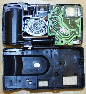
Figure 1. This single-use disposable camera can be used as a demo of a LC circuit that generates a high voltage to fire a flash bulb.
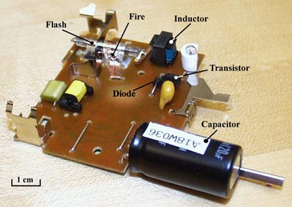
Figure 2. The electric circuit used in this camera
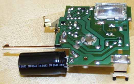
Figure 3. The vital electric components of the flash circuitry
It builds up the voltage by repetitively charging the inductor and transfering its energy into a conductor as shown in figure 4, 5 and 6. The inductor can be compared with its mechanical equivalent, mass. The inertia of an inductor can be used to force the energy into a capacitor. This can be compared with the inertia of the mass of a hammer that is used to pound a nail into a surface. The energy is then saved in the capacitor until the photographer presses a button. Via a mechanism a voltage is created at the flash fire wire, that is shown in figure 3. This causes the gas in the bulb to conduct the large voltage over the capacitor in a fraction of a second and generate the flash light.
Figure 4. Idealized and simplified model of the circuit
Figure 5. Switch in 'A' position: Charging of the inductor
Figure 6. Switch in 'B' position: Transfer of energy from inductor to capacitor