Pre-Lab (PDF)
Lab 6 Description (PDF)
This lab focuses on second-order electrical circuits, which contain inductors, resistors and capacitors. By measuring the step and frequency responses, the transfer functions can be determined. In figure 1, the idealization of this lab's circuit is shown.
Figure 1. Idealization of the RLC circuit used in this lab.
The input signal of the system is provided by a function generator. Because the function generator and inductor have internal resistances, a more accurate model looks like the circuit in figure 2.
Figure 2. RLC circuit with internal resistances of the function generator and inductor
The internal resistance of the function generator makes the output voltage vg differ from the desired input vi. Therefore an op-amp is used to work as a buffer, as shown in figure 3. Because the input impedance of the op-amp is very high and its output impedance very low, it forces vb to be almost equal to vi as long as the output current does not exceed the limits of the op-amp.
Figure 3. An op-amp buffer forces vb to be nearly equal to vi
The damping ratio can now be adjusted by varying the resistance R1. The resistor be seen as an electrical equivalent of a mechanical damper. Predicted responses of this circuit can be compared with measured ones. Figure 4 shows how magnitude and phase shift can be displayed on an oscilloscope using a sine wave from the function generator. By varying the input frequency, the circuit Bode plot can be generated.
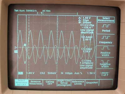
Figure 4. A sine input shows the magnitude and fase shift at a certain frequency